
Relic’s RetroPie Arcade Cabinet: Info, Tools & Assembly
(Assembly process images and final product coming soon! I just finished painting my build today and will post pics and a YT video asap!)
NOTE: This was printed on a Creality CR-10. A build area of at least 300x300x400 will be required. I used approximately 3 spools of Hatchbox PLA filament for this project with about 100 hours of printing time, but well worth it !!! Also, the only part not designed by me was the hinges. Not sure who had designed those but props to whoever you are!
Tools & Hardware:
⦁ 100 Grit Sand Paper
⦁ Epoxy (I used Devcon 2-part resin/hardner epoxy)
⦁ M4 Bolts and M4 T-Nuts – https://www.amazon.com/gp/product/B06ZZBNVTB/ref=oh_aui_detailpage_o04_s00?ie=UTF8&psc=1
⦁ Razor Blade and/or file set for part post-processing of supports
⦁ Generic USB Joystick Kit: https://www.amazon.com/gp/product/B01M2X88QP/ref=oh_aui_detailpage_o05_s01?ie=UTF8&psc=1
⦁ Raspberry Pi 2 or 3 with minimum of 16GB micro SD. I install Retropie on the SD and use the USB service turned ON to store ROMS on a USB flash drive. Here is the kit I purchased – https://www.amazon.com/gp/product/B0778CZ97B/ref=oh_aui_detailpage_o05_s00?ie=UTF8&psc=1
⦁ Various other cables may be required depending on your setup
⦁ Primer and paint if desired
⦁ Time and patience !!!
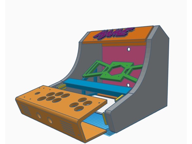
The cabinet is designed to fit many displays. The maximum display width is 350mm. A display with an aspect ration of 4:3 produces the best results as there is no black areas on the edges of the screen. Many new and used 4:3 displays can be found on Ebay.
This was also designed to use very few pices of mounting hardware. 4 M4 bolts are used to attach the monitor, 8 M4 bolts/nuts for the 3D-printed hinges, and 4 M4 bolts with hammerhead T-nuts are used to attach the control panel. 4 small machine screws hold the USB joystick controller in place. This leaves a very clean-look to the exterior of the cabinet.
ALL other joints use epoxy. The display itself also plays a role in keeping everything together. Refer to the images for assembly. My display had built-in speaker that sounded fine to me but you may choose to add your own. There are vents on the control panel ideal for adding stereo speakers.
The monitor viewing angle is 36 degrees. The size/shape of your display will determine where you actually epoxy the monitor mount and it’s supports. There are 2 side supports and 2 bottom supports. There is also a monitor bottom cover piece that is optional. I use it to give a nice finish to the area between the monitor’s bottom edge and control panel and also to hide the monitor buttons. Due to the shape of my display a bezel was not necessary. However if you do need one, design it 350mm wide and 2mm thick with a cutout to suit your display.
It’s VERY important to sand every joint where epoxy will be applied. Otherwise there will not be a strong bond. When done right, the plastic will break before the epoxy will.
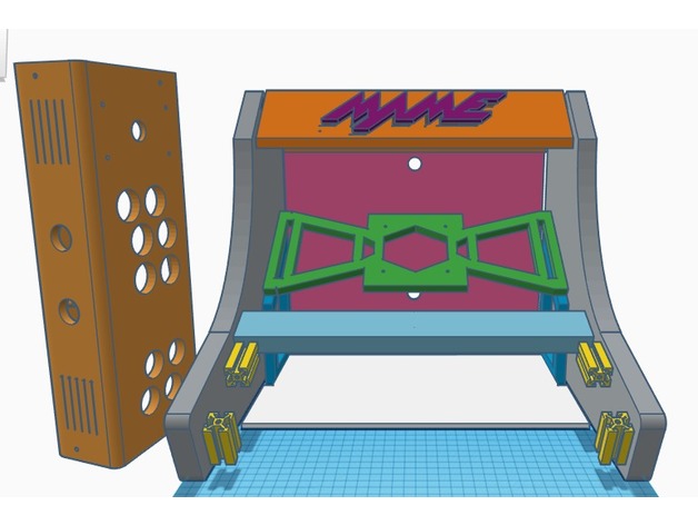
A model of 2020 slotted, extruded aluminum (40mm in height) was used for mounting the control board. Simply use epoxy to attach as illustrated. After the epoxy cures, use the T-nuts and M4 bolts to attach the panel.
Assembly:
Start by laying one of the sides down. Attach the monitor mount to your display and decide where the monitor SIDE supports need to be epoxied. Next epoxy the monitor side supports to each cabinet side. These supports hold the monitor mount in place. Remove the display and epoxy the monitor mount to the supports and sides as illustrated. After curing, re-attach the monitor and then epoxy the monitor BOTTOM supports in place. Allow plenty of time to cure.
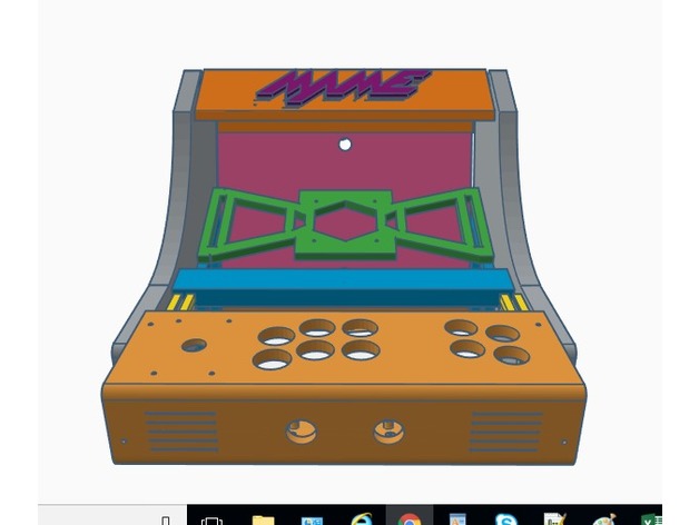
Turn the cabinet on it’s side and mock up the marquee support. It can be inset a bit if desired. Epoxy the marquee supports into place. After allowing to cure, the marquee should rest nicely on these supports and can be epoxied into place. Unless you plan to primer and paint, the MAME marquee logo can be inserted. Some filing may be needed to get it to fit as it will be very tight.
Mock up the control panel with the cabinet upright and then epoxy the 2020 extruded aluminum models into place. They should be centered with the control panel’s 4 mounting holes and be flush against the control panel. Wire up the control panel and attach to the 2020 models using M4 bolts and T-nuts.
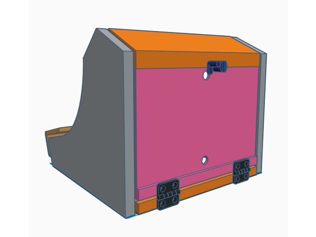
Epoxy the hinged back door BOTTOM and the bottom support piece into place. After curing, attach the 3D-printed hinges and back door. The top lock can now be assembled. The hole at the bottom of the hinged back is used to route your cables. I suggest a small power strip which can be attached to the bottom support piece. The RasPi case can also be attached here.
SVG files for “RetroPie” and “NEO GEO” are supplied for alternative marquee themes. Just import the marquee support into TinkerCAD, import the desired SVG logo and mix it up! Or, use these svg files to create side panel art/stencils.
Enjoy, and if you build this cabinet I’d LOVE to see it. Contact: [email protected]
How I Designed This
Build tools and process
All parts designed using TinkerCAD. I set out with only a side panel design in mind. So I designed every other part subsequently, starting with the monitor support after printing the 2 sides.
Remember – measure TWICE and design/print ONCE !!!
Credits:
relic
Download 3D models
| File | File size |
|---|---|
 RetroPie_Bartop_Arcade_Cabinet
|
1 MB |