
Hightower: A 3D-Printable Vertical Mini-ITX PC Chassis
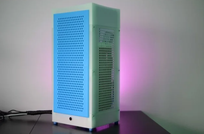
This is a Mini-ITX case in the style of the Xbox Series One, the Phanteks Evolv Shift, or the NZXT H1: it has a small footprint, but plenty of space inside.
This is designed to be printable on a Prusa i3 MK3S, so your printer needs a print volume of at least 250 x 210 x 210 mm. Please look at the printing settings for more information on how to best print the parts.
This is not a good model for 3D printing beginners to start out with, as it requires specific settings for specific parts.
Supports a two-slot graphics card with essentially no length limit.
Please look at the pictures of the assembled case, and read the 3D printing settings section for assembly instructions.
The assembled case is approximately 240mm wide, 210mm deep, and 520mm tall.
Custom Section
This model maxes out the bed size of the MK3S. You will need to turn off the skirt that PrusaSlicer prints by default in order to print the model.
It’s recommended to print this model in PETG, but PLA also worked in my tests.
Print Settings
Print all parts with at least two perimeters, preferably more.
fan_cover_base.stl and fan_cover_base_and_top.stl must be printed without top and bottom layers.
fan_cover_base_and_top.stl must be printed twice.
rubber_foot_4x.stl must be printed four times using flexible filament.
Print either section_base_cable_gasket.stl or section_base_cable_gasket_open.stl (not both) using flexible filament. Print the closed version if you’ve planned ahead and can route the cable through the gasket before the case is assembled, and the open version if you’ve screwed up and forgot to route the cables through the gasket ahead of time 🙂
For the top section, there are three different options:
section_top_flat.stl. This is easiest to print
section_top_rounded.stl. This is a bit harder to print, but looks cooler, as it has an indent similar to the Xbox Series X
section_top_rounded_square_vent_holes.stl is the same as the rounded version, but with a square arrangement of vent holes. This is required if you intend to use a larger fan (or if you prefer the looks)
Print one of the three options above, and print a corresponding fan holder. Print top_fan_holder.stl if you’ve printed either section_top_flat.stl or section_top_rounded.stl. Print top_fan_holder_square_vent_holes.stl if you’ve printed section_top_rounded_square_vent_holes.stl
Some parts must be printed with support. The following parts have optional built-in supports:
section_base.stl has a small support element around the IO shield opening
frontpanel_bottom_section.stl has a support element where the two front panel sections attach to each other that has to be removed after printing by pushing out the nubs
The following parts must be printed with slicer-generated supports:
section_power_supply.stl
section_top_rounded.stl
section_top_rounded_square_vent_holes.stl
Assembly
Please refer to the image of the exploded case, or the included STL of the exploded case to see how to assemble the case. You will need:
4 M3 4mm countersunk head for the front panel
12 M3 12mm to secure the individual sections
4 M3 12mm for the motherboard
4 M3 8mm for the feet
12mm power button (can be found on Aliexpress)
Optional 16 6mm diameter, 2mm height magnets for the front panel
Optional: 2 120 mm fans
Frontpanel Assembly
Remove the built-in support from the bottom section. Glue the two parts together, and secure them with 4 M3 4mm countersunk head screws. Insert 8 magnets if desired. Ensure that they are all oriented in the same way.
Motherboard Section Assembly
Screw the fully assembled motherboard into the section_motherboard.stl part
There’s around 150mm clearance for the CPU cooler
Also insert the graphics card at this time
Route the power cables from the motherboard at this point
Base Section Assembly
Remove the built-in support around the IO shield hole
Screw the four rubber feet into the section_base.stl model using four M3 8mm screws
Screw as 120mm fan in so it is on the underside of the base
Attach a fan_cover_base_and_top.stl print over the fan
Insert the gasket into the 40mm hole
Insert the 12mm power button into the hole at the front, and route the cables from the power button and the fan though the gasket
Check the picture of the base of the case if you’re unsure how to assemble everything
Slot the base section into the motherboard section, and secure the two using four M3 12mm screws
After the two parts are attached, use fan_cover_base.stl to cover the fan on the upper side
Power Supply Section Assembly
Slot the section_power_supply.stl model into the motherboard section, and secure the two using four M3 12mm screws
Route all cables now, including the power cables from the graphics card
Note that the cord going to the power supply needs to have a 90 degree plug on the power supply side
Top Section Assembly
Screw the second 120mm fan into the top fan holder print; look at the fan screw holes to determine which way the screws go in
Put the second fan_cover_base_and_top.stl print over the fan
Insert the top fan holder into your top section print, and push it all the way in
Slot the top section into the power supply section, and secure the two using M3 12mm screws
Finishing Touches
Insert the remaining front panel magnets into the case, if desired
Slot the front panel into the case. Make sure you slot in the upper side first, and then push in the lower side
If the blades of your graphics card fan touch the sides of the case, add a spacer at the top of the card
Credits:
V0XeL
Download 3D models
| File | File size |
|---|---|
 Hightower +Mini-ITX+PC+Chassis
|
8 MB |