
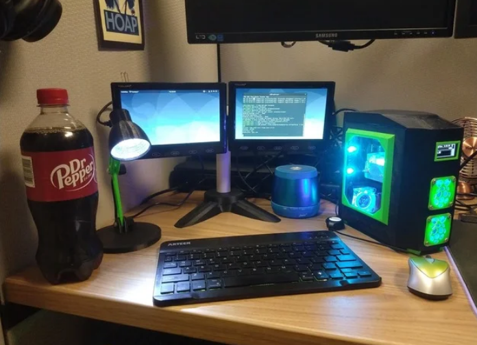
This is modeled to be proportional to a full tower case for the raspberry pi 4. it stands about 6 inches tall. If you make it, please please post a picture to feed my ego. I don’t mean to toot my own horn, but I find this really cool, and I would love to see yours. thanks.
list of things you will need.
- a raspberry pi 4 obviously
- HDMI right angle adapter.
https://www.amazon.com/gp/product/B08KXZHD9P/ref=ppx_yo_dt_b_asin_title_o03_s00?ie=UTF8&psc=1 - usb c extension to panel mount
https://www.amazon.com/gp/product/B075R7QBQD/ref=ppx_yo_dt_b_asin_title_o03_s01?ie=UTF8&psc=1 - hiletgo 1.3″ I2C screen
https://www.amazon.com/gp/product/B01MRR4LVE/ref=ppx_yo_dt_b_asin_title_o03_s01?ie=UTF8&psc=1
the above are what I specifically designed the case around. I doubt you will find another HDMI adapter like that, let alone with the same dimensions. the 1.3 inch screen you may be able to find different options with the same measurements, or else you will need to modify the model.
everything else offers a little more wiggle room.
- ice tower cpu cooler (depth on this ended up being close, more bleow)
https://www.amazon.com/gp/product/B07V35SXMC/ref=ppx_yo_dt_b_asin_title_o03_s00?ie=UTF8&psc=1 - geeekpi fans (or any 40mm fan, they should mostly all line up)
https://www.amazon.com/gp/product/B084RCBSBX/ref=ppx_yo_dt_b_asin_title_o03_s00?ie=UTF8&psc=1 - fan header (or something to let you hook up all the fans, as the raspi only has two 5v pins)
https://www.amazon.com/gp/product/B07BWFT253/ref=ppx_yo_dt_b_asin_title_o01_s00?ie=UTF8&psc=1 - RGB lights (these are NOT optional, every good pc needs RGB… well ok, they are optional, but i did design something around this remote specifically)
https://www.amazon.com/gp/product/B07QJ46KB9/ref=ppx_yo_dt_b_asin_title_o02_s00?ie=UTF8&psc=1
most of the parts are fairly self explanatory, and are already in the optimum printing position. they are all oriented so that the outside facing will be on the print bed, in my case I used a glass print bed, so most of the outer surface of the case is nice and shiny and smooth. I found the HDMI ports were a little wiggly so i updated the io plate. V2 has a piece that goes between the ports which have a small screw hole, as well as a little lip that the cube part of the ports will sit inside.I have yet to find a screw that fits the hole between the hdmi ports, but with the IO plate glued into place, the lip i have around the ports seems to hold it a lot better than the original.
Most don’t need supports, the “Top” piece printed without supports on my ender 3, but the overhang angle was a bit steep, so I probably should have used supports on that. It came out a little wavy on the angled parts. The “Right Side” might need supports for the screw holes, as its designed for the screw heads to be recessed. again, i printed mine without, and while messy looking, it worked and held the pi just fine.
there are front and rear feet, that are optional, but there is also rear feet with a holder for the rgb remote to slide into. its a tight fit by design so you might have to smooth out the edges a little to get it in there, but I didn’t want it falling out.
there are also 2 trims to go around the window, a flat one and an offset one. i had some scrap plexiglass laying around, but it was a bit too thick, so i used the offset trim so the plexi didn’t hit the cpu fan. if you get a thinner piece of plexi or glass, you can probably use the flat one.
everything i bought included screws except the I2C display, you will need to find some short M3 screws, or i guess you could probably hot glue the screen in place. There is a small screw hole in between the hdmi ports. i dont have a screw in mine and it holes them fairly well. of course if i can find a screw that small i will put it in. you will also need eight 6mm magnets to hold the left side on. the holes in the side panel are 7mm, so they should fit easily. the holes in the case are a little smaller, they will require some patience, trimming, and a piece of tape on the back when you glue them so the glue doesn’t run through. Also notice the outline of the holes on the case are spread across the 4 pieces, so like if you put the bottom in upside down, the part of the holes will be on the wrong side of the case. sorry, the magnets were a bit of an afterthought and i admittedly could have probably designed it a bit better, but it worked out well for my build.
I put the RGB lights up the back, across the top, and down the front. it totaled 11 individual lights. That combined with the 4 fans draw about 500ma, so it should be fine running all that from one of the 5v pins like i have it. I both did the math on it before purchasing it, and I plugged the pi into a usb charger that shows current draw. at idle without the fan header plugged in it sat at about 350ma, with the fan header it fluctuated a little between 750ma and 850ma. The I2C display uses 3v3 and draws negligible current.
Assembly:
you may want to get your SD card set up before putting this together. its not impossible to get the sd card in and out, but its not easy. i thought about getting a relocation adapter. you can find them on amazon by searching “micro sd card extension.
EDIT: i bought an SD card extension and made a little riser to put it in the bottom of the case, see pictures. this makes removing the SD car a whole lot easier
I found it easiest to put the raspberry pi and hdmi board on the right side, and put the display screen and the fans and grills on the front and back pieces, before gluing everything together. The ice tower cooler comes with 8 standoffs and 4 screws. i put the standoffs up through the bottom of the pi, so that the nuts are on top. then you use the screws to mount that to the right side from the outside. i made a crude representation of this in the pictures.
the hdmi board came with 2 screws, and those just screw into the plastic posts on the right side.
i found the best order to put it together was to glue the top to the front, since those edges line up pretty well, and the added angles make getting those at a perfect right angle pretty easy. i then glued the right side, with the pi, hdmi board, and ice tower connected to it. now you can get the back side lined up and test fit the IO plate into it. the IO plate may require some sanding on the top or bottom to get the ports to line up exactly. I updated the IO plate to V2 that should hold the hdmi ports a little more secure. Once you get those to lined up screw the usb c connector to the io plate and glue them in place. you can see in one of the pictures how i looped the usb c cable to get it to fit. it did require a little bit of convincing.
At this point i put the fan header in and hooked up all the wires. i put the fan header plug across pins 4, 6, 8 and 10. which are 5v, ground and gpio 14 and 15. so there is one lone 5v pin not hooked up. i originally had it across the 2 5v pins, ground and just gpio 14, but there was something in the fan header that didnt like using the third pin. i put a picture of this as well. You could cut the end off the fan header and put dupont connectors on there, but i didnt really need GPIO 14 and 15, so i just stuck the fan plug on there and it fit fine after trimming the little tabs off. The side that the tabs were goes toward the heat sink (up in the picture.
your I2C screen (if you bought the same one as me) will plug into pins 1, 3, 5, and 9. (check with the documentation of your particular screen. i used this guide.
https://luma-oled.readthedocs.io/en/latest/hardware.html
when running a script you have to specify sh1106 for the screen i bought.
once you have everything in there, glue the bottom piece in. it has cutouts for the magnets on one side. the side that was on the print bed should go toward the bottom of the case. the holes for the magnets on the left side are 7mm, so 6mm magnets should just drop right in. a dab of super glue will hold them fine. the holes on the case are 6mm, so you will need to trim them a little. i wanted them to be tighter since i didnt design them as well. they dont have a solid back to them. what i did was trimmed until the magnets fit snug. then put a piece of tape across the back, then put some superglue around the edges, once that dried i peeled the tape off. they dont hold a lot of weight so this seems to work pretty well.
i think i covered most of the less obvious stuff, of course if you have any questions post a comment, i try to check here every few days.
edit:
i ordered this
https://www.amazon.com/gp/product/B07WWVBK8V/ref=ppx_yo_dt_b_asin_title_o00_s00?ie=UTF8&psc=1
and added a riser to put it in the bottom of the case. i ran my fan header cable slack, and have the rgb contoller hot glued in the bottom. this should raise the card slot up enough to make it really easy to access. will update when i get the part printed and teh sd adapter in the mail.
Printer brand: Creality
Printer: Ender 3 Pro
Rafts: No
Supports: No
Resolution: .32
Infill: 10
Filament brand: Hatchbox
Filament material: PLA
Notes:
i printed mine at .32 because im impatient, but the top and front could probably benefit from a higher resolution since the layer lines are more evident in them.
Credits:
Lunchbox7985
Download 3D models
| File | File size |
|---|---|
 Mini+Pi+Desktop
|
4 MB |