


UPDATES:
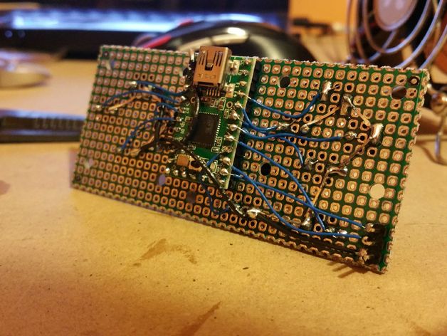
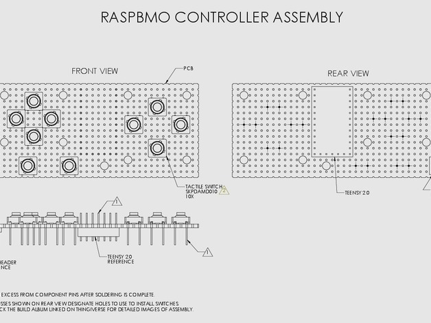
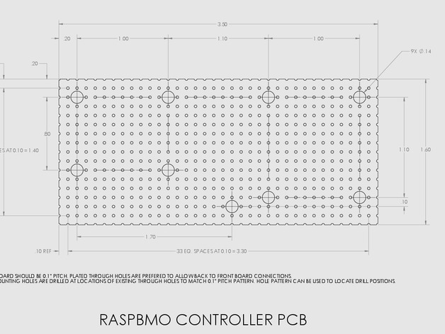
(3/8/15) PDF drawings detailing how to construct the USB controller for this project have been added under the source files. To create the PCB follow the ‘Controller Perf Board’ drawing. To assemble the controller follow the ‘Controller Assembly’ drawing as well as the pictures in the build album. For wiring the controller a schematic has been added under ‘Controller Schematic’.
(3/14/15) Added zip files containing all parts as both Solidoworks and STEP part files in case anyone would like to modify some parts. Also added the Arduino code for the Teensy in the controller.
(3/29/15) Added PDFs of schematic for routing board as well as wiring guide for Raspberry Pi A+ to Thing Files. Also added link below to Youtube video (Credit to Floob) to help set controller in Retropie.
(4/27/15) Added link below to Youtube video (Credit again to Floob) to help set up controller for MAME.
Intro:
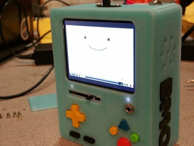
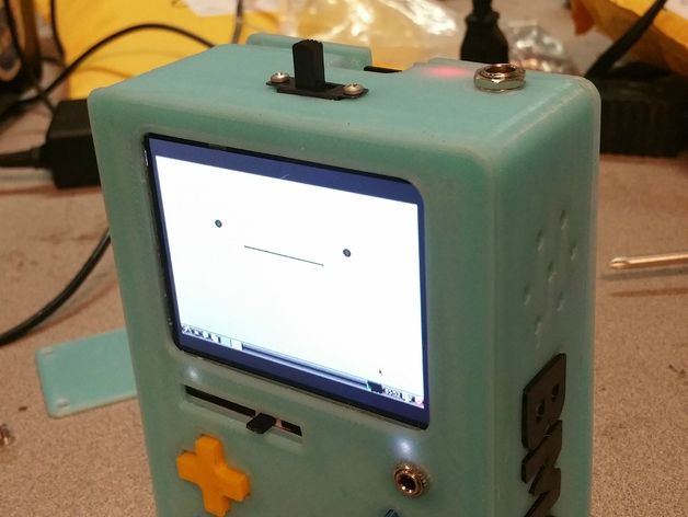
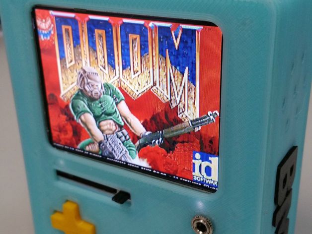
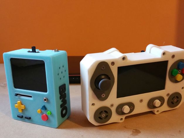
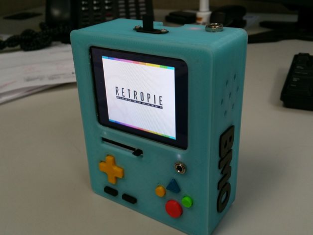
Presenting my second handheld emulator project based on everyone’s favorite sentient game console. The specs are as follows:
Overall size: 4″ X 5″ X 1.75″
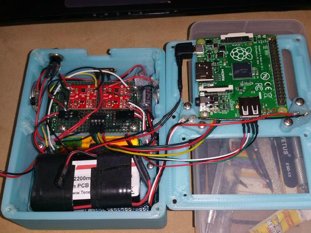
CPU: Raspberry Pi A+
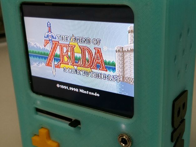
Operating System: RetroPie
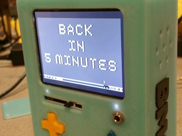
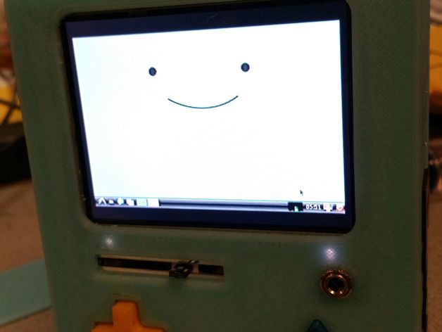
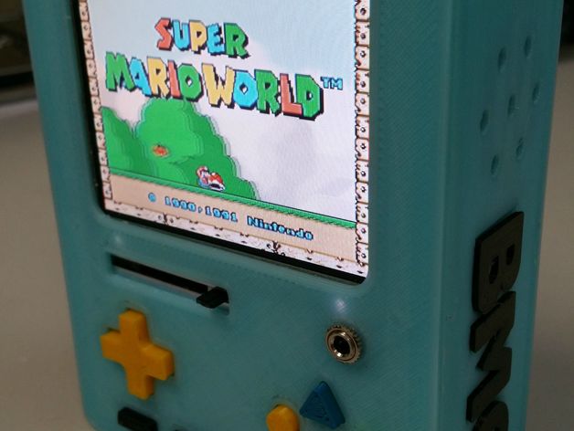
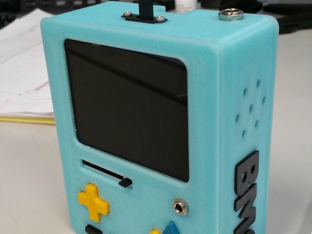
Display: 3.5″ TFT
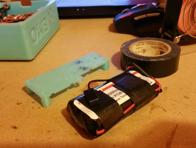
Power: 7.4V 2200 mAh Li-Ion
Controls: Fully set of SNES (D-pad, 4 actions, start/select, L/R) buttons built around a Teensy 2.0 HID device
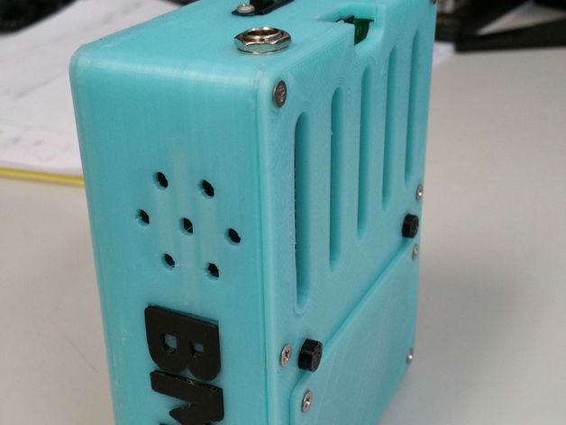
Sound: Stereo Speakers with slide potentiometer volume control and headphone jack
Video of the console in action can be found HERE
Video of the first boot can be found HERE
An overview album for the project can be found HERE
An album of the powered up pics can be found HERE
An album of glamor shots can be found HERE
A (massive) construction album is located HERE
An album detailing construction of a charger adapter is HERE
A detailed Bill of Material can be found HERE
A video link to help set up the controller can be found HERE
A video link to help set up the controller for MAME games can be found HERE
A small write-up of the project can be found in the instructions section.
Instructions
Instructions are currently WIP. I hope to have a set of schematics as well as some general instructions out in the coming weeks. Feel free to ask any questions in the comments.
In the meantime I will add a small write up describing the main components of the system. I hope to follow this up soon with some schematics/instructions.
Caution, I am not a professional when it comes to the electronics in this project. If any of my instructions/schematics seem incorrect please disregard them and be sure to comment and let me know. Caution
Main Components:
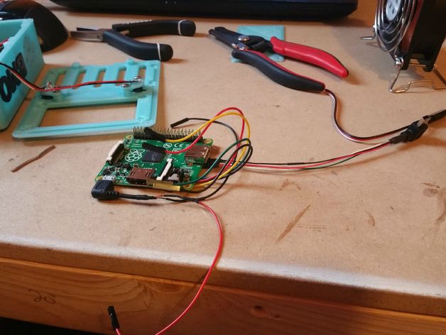
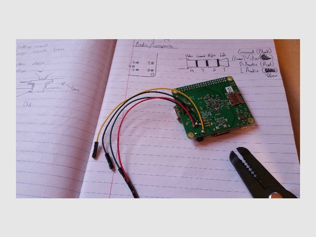
-Raspberry Pi A+: The heart of the project. It uses an image of Retropie as its OS. The 256M of Ram is split evenly between the CPU and GPU. The composite video and stereo outputs (on the 4-pole jack) are utilized internally for this project. To save space the 4-pole jack was ignored and the connections wired directly to the solder tabs on the board. HDMI was utilized initially during construction for setup purposes. If you have an issue with the Rpi not outputting composite video add the line hdmi_ignore_hotplug=1 to the config.txt file. This will completely shut off HDMI output so in case you need it again you can use your PC to edit the above line out of the config.txt file. 5V power is regulated to the Pi by using a UBEC wired to the main 7.4V power line.
-3.5″ TFT Display: The display linked in the bill of material is intended for use with a vehicle backup camera. However, it can easily be utilized as a cheap display for Raspberry projects. Being a vehicle display it is designed to run on 12V power, however, from testing I determined it to run smoothly (though inefficiently) on 7.4V. Research online points out that these displays can be modified to natively accept 5V power however a modification like this seemed slightly out of my comfort zone. Out of the box the screen is packaged in a hard plastic case. This case will need to be carefully removed to retrieve the raw display inside. The only modification the display needed was to have its stock wiring replaced with a servo cable to delivery power, GND, and composite signal.
-7.4V 2200 mAh Li-ion Battery Pack: The main power source of the project. First a word of caution! Li-ion batteries can be dangerous if mishandled. Be sure to double check your wiring as well as any system schematics to ensure everything is wired properly. And be sure to use a charger designed for this kind of Li-ion pack. The battery listed in the bill of material comes stock with no connector. For my build I used the 2-pin female header removed from the UBEC as the battery connector. The 7.4V battery power is supplied to the system as a whole. The display and UBEC are wired in parallel to run directly off this 7.4V. The UBEC then regulates the power down to 5V for the Raspberry Pi and speaker amplifiers. The power switch for the case is actually a DPDT (though only a SPDT is required) one throw of the switch connects the battery to the system and is essentially the ‘on’ state. The other throw disconnects the battery from the system ‘off’ and connects the battery to a coaxial connector on the case. This coax connector, when combined with an adapter cable built for the charger, can be used to charge the battery without removing it from the case.
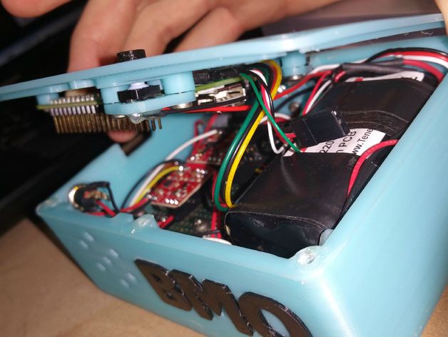
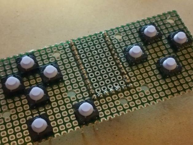
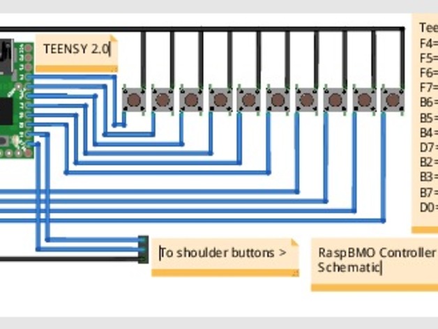
-Controller: The main portion of the controls is built onto a perf-board, details of it can be found in the build log. The switches for the D-pad, action buttons and start/select buttons are soldered to one side of the board while the Teensy 2.0 is soldered to the other side. The wiring for the buttons consists of one side of the switches wired to individual I/O pins on the Teensy while the other side of the switches are bussed together to the Teensy GND pin. The programming for the Teensy is set up using the Teensyduino script to run the Teensy as a joystick HID. Instructions for this can be found on the Teensy website. The main board has a 3-pin header to bring the L/R shoulder buttons from the rear of the case to the main board.
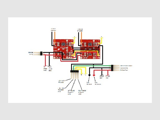
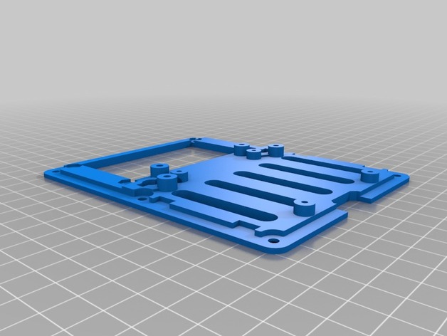
-Routing Board (Optional): in order to organize the case wiring I built a routing board to keep the wiring to a minimum. This board handles the signals for the Audio amplifiers as well as the display. It also routes power to each of the main components. The speaker amps and Raspberry Pi are both wired in series to the 5V UBEC output using this board. The UBEC and display are also wired in parallel to the main battery using this board. If this aspect sounds a bit confusing its because it doesn’t lend itself to a write up. I hope to supply a schematic for this board in the near future.
-Sound: The sound system for this project consists of two halves. First is the stereo speaker system utilizing two 8 ohm speakers and separate left and right amplifiers (from Sparkfun). This section draws left and right audio signals directly from the Raspberry Pi. 5V regulated power is supplied to these amplifiers by the UBEC. The second half of the sound system is the stereo headphone jack. This jack draws from the same L/R Rpi audio signals as the stereo speakers.
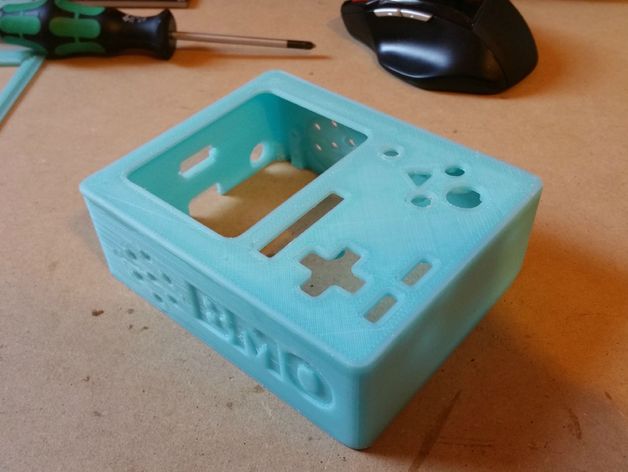
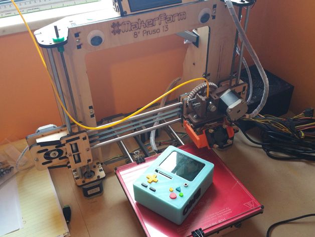
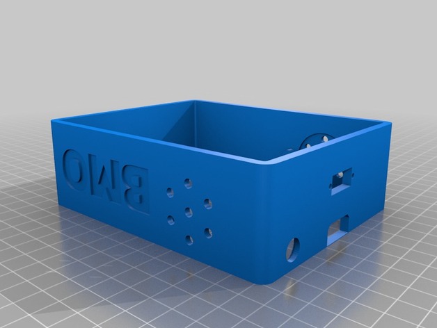
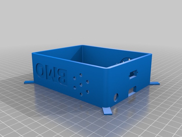
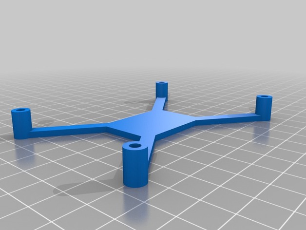
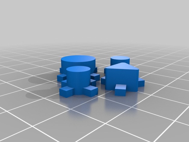
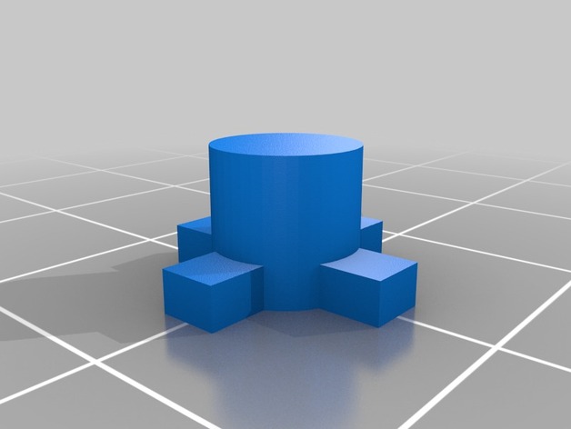
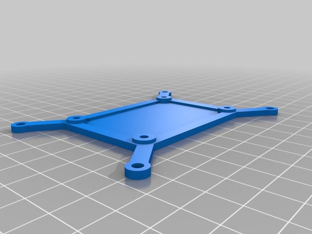
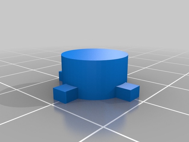
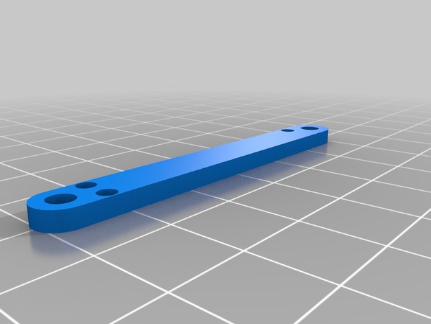
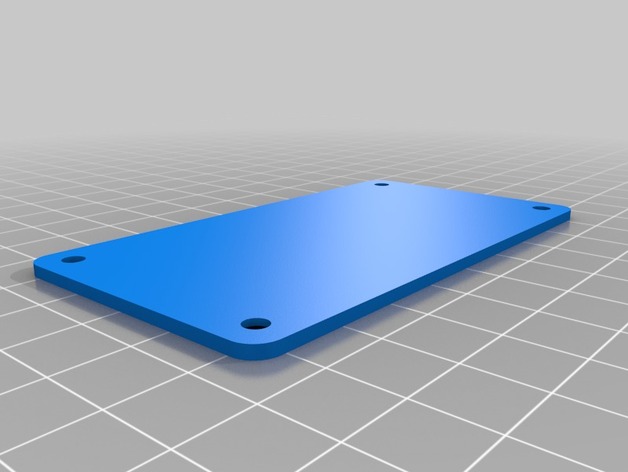
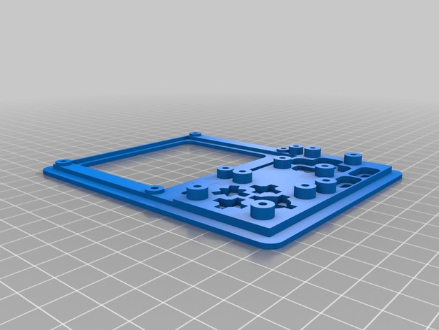
-3D Printed Case: I printed the case parts at 0.4mm to save time, overall the results were pretty decent. Two points of note. First, the front face is held to the shell using epoxy. Any cheap two-part epoxy should work here. I found the best practice here was to spread the mixed epoxy onto the edges of the shell using a plastic butter knife and then firmly press the front face over top. Be sure to get the orientation correct! Place a heavy object over top the two parts while the epoxy cures to ensure a strong seal. The other point of note is the locking mechanism used for the hardware in this project. To keep the design clean and simple I ignored hex nuts for locking purposes and instead focused on using the plastic itself as the captive hardware. To do this the holes in the case into which screws are inserted are slightly undersized for their perspective screw. This means that upon first install you will have to give the screw a few strong turns to tap threads into the plastic. In my experience this leads to good sturdy hardware connections about 90% of the time. On the off chance you wind up with a mounting hole too loose to properly hold a screw I found that adding a bit of hot glue into the hole helped to create a good connection. My advice would be to pick a small part to print as a test (potentially the front face) and make sure that your print settings are dialed in correctly to print out the properly sized mounting holes.
NOTE: Even if you don’t want to complete the entire emulator project, I believe the case could make a pretty decent BMO replica. An interesting idea mentioned in the comments on Make.com mentioned replacing the video game console components with servos and making a little BMO robot which sounds awesome to me.
Credits:
3Derp
Download 3D models
| File | File size |
|---|---|
 RaspBMO_Handheld_Raspberry_Pi_Emulator
|
12 MB |