
Silent Clock
This is a silent Clock for wall mounting or to place on a flat surface. It is designed from the ground up to be easily printed so you should have no problem with it – only a single part needs supports (the wall hanger). The maximum required print area is 180 mm x 180 mm (I used my Prusa mini as upper limit)
The clock is designed around common parts readily available online like a 5V Stepper motor, a Arduino nano and a common RTC and bearings. A more specialized component is the silent step stick which is the ultra quiet stepper driver. However you can try these common stepper drivers for 3d printers and see if they are sufficiently quiet.
Many of the parts are designed to support two-color printing via M600 command (changing filament mid print) by incorporating stepped design accents (mostly the gears and the clock face). For materials you can print everything in PLA if you wish. I myself printed the Wall Hanger (M25), the cable strain relief (M28) and the legs (M26, M27) in PETG. The remainder was mostly printed in galaxy black and pineapple yellow PLA.
I’m not an artist, I tried my best to create something simple but neat looking. If you want to make your own clock face I can create a drawing with the required mounting points.
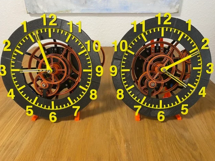
For the two or three people in the world which like me prefer a counter clockwise spinning clock there is a variant of the clock face in the files folder. To spin the clock backwards only a single line in the code has to be edited.
The clock is set by disengaging the spring loaded gear of the stepper motor and tuning the handles manually. The RTC clock chip is only used as very precise 1 Herz Clock source.
Part List
All components have an identifiers. Parts to buy have the prefix “B” and all parts you have to make/print are marked with the prefix “M”. The screw types are not very well optimized, I just used what I had at hand at the time. At some parts you may get away with shorter/longer bolts.
I hope you can overlook the frequent occurrence of “watchface”, I only found out later that this is not an actual English word – sorry about that.
The fact that M20 is called Battery holder can be ignored for now. In theory this clock can be conveniently battery powered, however the run time is still way too bad. Maybe I will release a retro-fit design in a few moths to fix that and make battery powered operation feasible.
Parts to buy
| Part Number | Quantity | Part Name | Description |
|---|---|---|---|
| B01 | 5 | B01_Bearing7/22/8 | Standard Bearing |
| B02 | 1 | B02_Stepper_Motor | Stepper Motor 28BYJ-48 ULN2003 |
| B03 | 1 | B03_Arduino_nano | Arduino Nano |
| B04 | 1 | B04_Stepper_driver | Silent Step Stick |
| B05 | 1 | B05_RTC_PCB | Real Time Clock AZDelivery RTC DS3231 |
| B06 | 1 | B06_coil_tensioned | Small coil |
| B07 | 2 | B07_M5x20 | M5x20 Screw, any head |
| B08 | 1 | B08_M5x24 | M5x24 Screw, any head |
| B09 | 1 | B09_M5x35 | M5x35 Screw, any head |
| B10 | 2 | B10_M4x8_flathat | M4x8 Screw, flat head |
| B11 | 13 | B11_M4x10_flathat | M4x10 Screw, any head |
| B12 | 1 | B12_M3x30 | M3x30 Screw, any head |
| B13 | 32 | B13_M3x12 | M3x12 Screw, any head |
| B14 | 6 | B14_M3x8 | M3x8 Screw, flat head |
| B15 | 2 | B15_M3_washer | M3 Washer |
| B17 | 2 | B17_M2x8_flathat | M2x8 Screw, flat head |
Parts to print
| Part Number | Quantity | Part Name | Description |
|---|---|---|---|
| M01 | 1 | M01_Base | Base Plate of the device |
| M02 | 1 | M02_gear_a | Gear a |
| M03 | 1 | M03_gear_b1 | Gear b1 |
| M04 | 1 | M04_gear_b2 | Gear b2 |
| M05 | 1 | M05_gear_c1 | Gear c1 |
| M06 | 1 | M06_gear_c2 | Gear c2 |
| M07 | 1 | M07_gear_d1 | Gear d1 |
| M08 | 1 | M08_gear_d2 | Gear d2 |
| M09 | 1 | M09_gear_e | Gear e |
| M10 | 4 | M10_Bearing_cap_M5 | Cap to screw in M5 bolt |
| M11 | 1 | M11_Motor_arm | Arm to swivel the stepper motor |
| M12 | 1 | M12_Motor_mount | Part to mount the stepper motor |
| M13 | 1 | M13_mount_stand_gears_d | Connects base with d-gear mount |
| M14 | 1 | M14_mount_arm_gears_d | Holds in place bearing of d-gears |
| M15 | 1 | M15_e_bearing_adapter | Standoff to mount minute handle to gear |
| M16 | 9 | M16_WF_Holder | Holds the Watchface in place |
| M17 | 3 | M17_WF_clamp | Watchface Mounting gear |
| M18 | 1 | M18_WF_TRBR_clamp | Clamp to fix watchface sub-parts |
| M19a | 1 | M19CW_c_Watchface_BR | Watchface top right |
| M19b | 1 | M19CW_a_Watchface_TL | Watchface botton right |
| M19c | 1 | M19CW_d_Watchface_BL | Watchface bottom left |
| M19d | 1 | M19CW_b_Watchface_TR | Watchface top left |
| M20 | 1 | M20_Battery_Holder_Mount | Mouting Point for PCBs and Batteries |
| M21 | 1 | M21_PCB_mount_Arduino | Mount for the Arduino nano |
| M22 | 1 | M22_PCB_mount_RTC_Stepperdriver | Mount for RTC and Stepperdriver |
| M23 | 1 | M23_Handle_h | Hour Handle |
| M24 | 1 | M24_Handle_m | Minute Handle |
| M25 | 1 | M25_Wall_mount | Wall Hanger |
| M26 | 1 | M26_Desk_Stand_Left | Desk Stand Left |
| M27 | 1 | M27_Desk_Stand_Right | Desk Stand Right |
| M28 | 1 | M28_Cable_clamp | Strain relief for USB cable |
Parts which can be printed together in one operation:
- M02_M03_M04_M06_M07_M08_M09
- M10_M12_M13_M14_M15_M20_M21_M22
- M16_M17_M18
Additional parts
- USB Cable to power the clock (USB 2.0 is sufficient)
- USB Charger
- maybe two small felt pads to not scratch the wall painting when wall mounting
The current draw is less than 500mA so any USB charger should work
Prerequisites to build this clock:
- Soldering iron
- Basic electronics skills to wire everything up
- Knowledge on how to flash an Arduino with the provided code
- M3, M4 and M5 thread cutters
- Small wires to interconnect the electronic components
- Pliers and scalpel or small box cutter to cut PCB trace of stepper motor (see Assembly Note 1)
- Small flat head screwdriver and Multimeter to adjust motor current
Assembly
I created an animation which shows step by step how to assemble the clock. It is quite fast paced, just pause it at every step. In the video there are a few callouts to Assembly notes, these are covered here:
Assembly Note 1:
Stepper Motor Modification:
To make the clock as quiet as possible the normally unipolar stepper motor 28BYJ-48 ULN2003 is modified to be bipolar. João Brázio from the website Ardufocus shows how to do it. Basically you want to cut a single PCB trace (check with multimeter afterwards that the trace is cut)
https://ardufocus.com/howto/28byj-48-bipolar-hw-mod/
You can remove the end of the cable with the connector, we don’t need it, as well as the red cable in its entirety.
Assembly Note 2:
Wire up Arduino, Stepper driver and stepper motor.
Face the Arduino with its USB plug upwards (as in the video) and face the motor connections of the silent step stick in the direction of the stepper motor (M1A .. M2B). Connect the wires as shown in the wiring diagram:
| Arduino | Stepper Driver | Stepper Motor |
|---|---|---|
| D11 | EN | |
| D12 | DIR | |
| D13 | STEP | |
| 3V3 | VIO | |
| 5V | VM | |
| GND | GND near VM | |
| M2B | Dark Yellow | |
| M2A | Pink | |
| M1A | Bright Yellow | |
| M1B | Blue |
Optionally you can remove the small resistor besides the red pwr LED so that the Arduino does not glow in the dark (recommended).
Assembly Note 3:
Wire up the RTC:
First, if you bought the cheap AZDelivery RTC DS3231 like me with a battery instead of an rechargeable battery you want to remove the diode between the IC and the four-pin connector. A forced charging with this diode of a non-rechargeable battery is a fire hazard.
We have to cut off the six-pin pinheader because the RTC would otherwise be too tall to fit under the clock face. Remove the battery while doing so to prevent accidental shortcuts. Plug the battery back in after removing the pinheader.
Now you can wire up the RTC:
| Arduino | Stepper Driver | RTC |
|---|---|---|
| D2 | — | SQW |
| A4 | — | SDA |
| A5 | — | SCL |
| — | GND near VIO | GND |
| — | VIO | VCC |
Optionally you can remove the small resistor besides the red pwr LED so that the RTC does not glow in the dark (recommended).
Now is also a good time to flash the Arduino with the provided firmware:
https://github.com/mariuste/SilentWallandDeskClock
Shout-outs:
I want to thank Nico Schlueter for providing the awesome free gear making plugin “Helical Gears Plus” for Fusion 360. I created all gears in this design with it:
https://apps.autodesk.com/FUSION/en/Detail/Index?id=1259509007239787473&os=Win64&appLang=en
For preparing the release of this design I used the Fusion 360 Plugin Bommer by Jesse Rosakia and James Ray extensively. As the name implies it is very useful to create semi complex Bills of Material which allowed me to track my progress in various stages of the design.
To safe some time I used the following libraries in my code. They are available in the Arduino library manager
“StepperDriver” by Laurentiu Badea v1.3.1
“DS3231” by Andrew Wickert, Eric Ayars, Jean-Claude Wippler, Northern Widget LLC v1.0.7
Printer: Prusa Mini
Rafts: No
Supports: No
Resolution: 200
Infill: 20
Filament brand: Prusament
Filament color: Galaxy black, Pineapple Yellow, Orange
Filament material: PLA, PETG
Credits:
mariust
Download 3D models
| File | File size |
|---|---|
 Silent+Wall+and+Desk+Clock
|
11 MB |